A few words of advice for people building this
- When you populate the board, build the power supply section first and test it to make sure it works. You don't want to find out your buck converter is not working when smoke comes out of your op amp or PIC18F.
- The adjustment of the trim pots in the positive temperature coefficient (PTC) amplifier is explained in a readme file in the hardware section. This adjusts the constant current source into the PTC thermistor.
- Remove sensor from PTC connector
- Attach milliampermeter to PTC connector
- Power the device on
- Turn CAL1 pot until you get exactly 1.000mA going trough.
- Once you have the current source trimmer set, set the gain as follows.
- Remove sensor/milliampermeter and connect a 100 OHM resistor (1% or better) to PTC connector.
- remove jumper from JP1
- Power on device
- Turn the RV2 pot until you get on the top pin of JP1 exactly 3.00V
- I had problems with the heater control section. It turns out the opto-triac was bad. Not sure if I received a bad one or I fried it somehow. I ended up picking up a non-zero-crossing opto-triac at the local All Electronics. In case you were wondering, a non-zero-crossing works just fine.
- Arhi recommended not installing the capacitors for the low-pass Sallen-Key filter. I didn't see that warning until after installing them. They actually worked well with a time constant pretty close to the calculated value so I left them in.
After the board was fully populated, except for the NTC and the thermocouple amplifier sections, I squeezed everything into a plastic box. The enclosure was actually a container for Korean pepper paste (gochujang). I was impressed with Egor who correctly identified the container from a front/side shot.

Here is a picture of the top clearly showing its source.

I hooked up buttons for menu, + and -. These were interrupt driven and the switch bounces caused a lot of problems. Arhi wrote a debounce routine but the button presses were limited to 5 per second and there was no autorepeat which made adjusting the temperature a bit tedious.

I hooked up buttons for menu, + and -. These were interrupt driven and the switch bounces caused a lot of problems. Arhi wrote a debounce routine but the button presses were limited to 5 per second and there was no autorepeat which made adjusting the temperature a bit tedious.
I rewrote the debounce code and added autorepeat. This made the interface much easier to use. I posted the changes in the forum http://dangerousprototypes.com/forum
Here is a shot of the inside.
 I need to secure the circuit board inside. There is a lot of empty space inside and I am always short on benchtop space. If I am motivated, I might move everything into a smaller enclosure (Korean soybean paste (doenjang) container perhaps). I will have to use a smaller LCD display (8x2 characters) and rewrite the firmware to be more succinct and frugal.
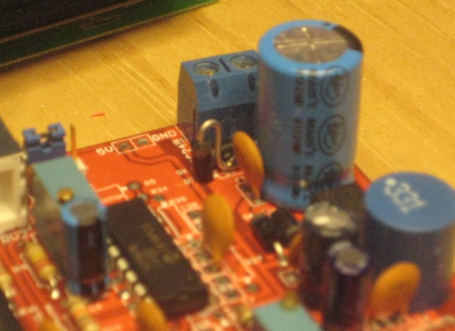
Here is a shot of the completed circuit board. In the second picture, you can see the diode lead art for the bridge rectifier. The capacitor to the right of the diode was a bit big and the diode was squeezed for space. There is another diode standing upright just behind the cap as well.


The transformer was salvaged from a lab freezer controller board. It has multiple primary windings for different input voltages and two separate secondary windings. In its current configuration it puts out 20V AC. Even after its been on for an hour, I can't detect a temperature increase above ambient. The triac gets a bit warm, possibly because the input voltage is lower than the expected 24V so I am going to put a heatsink on it.

Here is a shot of the completed circuit board. In the second picture, you can see the diode lead art for the bridge rectifier. The capacitor to the right of the diode was a bit big and the diode was squeezed for space. There is another diode standing upright just behind the cap as well.

The transformer was salvaged from a lab freezer controller board. It has multiple primary windings for different input voltages and two separate secondary windings. In its current configuration it puts out 20V AC. Even after its been on for an hour, I can't detect a temperature increase above ambient. The triac gets a bit warm, possibly because the input voltage is lower than the expected 24V so I am going to put a heatsink on it.
Addendum: I have received several requests for precompiled binaries. I have uploaded the modified source along with the compiled binaries (with and without bootloader versions) to github. You can get them at
https://github.com/hardwhack/Soldering-iron-driver
Hi,
ReplyDeleteCan you post or e-mail me (dino_slmn@yahoo.com) your last working Hex for buttons?
Have same problem with Hakko 907. I don't know if is original or clone. have a 42 ohm PTC
Thank
Dino
So ..i looking for last working hex for buttons.I have a weller wsp80 with pt20 sensor.
ReplyDeleteThanks and you could use my email adress ioachim.wilhelm@gmail.com
See addendum above. Binaries now available at github.
DeleteHello,
ReplyDeleteWhich kind of programmer was used for compiling ?
I try Mplab X ide with xc8 and not works.
I had the same problem compiling with xc8. Arhi wrote the firmware to the older c18 compiler standards. I remember scrounging through all corners of the internet to find it-- especially hard to find the Mac OS versions. Sorry but I can't remember where I found it.
ReplyDeleteThank,
ReplyDeleteI find the mplab 8.6 and c18 for windows
I will try. I am not a programmer . Only for my curiosity.
Hi, would be kind and describe the power section assembly and testing please? I'm on my second board (could not get first one working), I have assembled D2, D3, D4, D5, D6, C8 and C9. I'm getting 46v across DC/DC and 4v ac across the 5v test pin. Is that correct?
ReplyDeleteCheers!
Amazing! It's very helpful resource. I loved it. Keep writing more soldering iron tips
ReplyDeletePlease let me know if you’re looking for a article writer for your site. You have some really great posts and I feel I would be a good asset. If you ever want to take some of the load off, I’d absolutely love to write some material for your blog in exchange for a link back to mine. Please send me an email if interested. Thank you! budget soldering iron
ReplyDeleteRC Jet
ReplyDeleteSoldering iron
Sky Flight Rc Jet
kerui Security alarm
weller soldering
Flightline RC Plane